
Date: December 30, 1998
Models: 1994-1999 BR/BE Ram
Note: applies to vehicles with 3.9L, 5.2L and 5.9L engines (gas)
1994 – 1999 (AN) Dakota
1994 – 1999 (BR/BE) Ram Truck
1998 – 1999 (DN) Durango
1995 – 1999 (XJ) Cherokee
1994 – 1999 (ZJ) Grand Cherokee
Symptoms: some vehicles may exhibit one or more of these symptoms:
- spark knock complaints with vehicle under load
- various single cylinder misfire (1, 3, 7,) ad especially 5 and/or 8
- surge in 4th gear with the Electronically Modulated Converter Clutch (EMCC) engaged (around 45MPH).
- Perceived torque converter EMCC engagement/ disengagement around 45 MPH.
Diagnosis:
Using the Mopar Diagnostic System (MDS/MDS2) or the Diagnostic Scan Tool (DRB III), verify that all engine/transmission systems are functioning as designed. If other DTC’s are present, repair as necessary before proceeding with this bulletin. If no other DTC’s are present and the above symptoms have been reported by the customer, perform the repair procedure.
NOTE: This rerouting procedure should be performed before any other misfire, surge, or spark knock repairs are attempted.
Parts:
3 56028186 Clip, single wire
2 06503441 Clip, wire to hose (5.2L, 5.9L)
1 04364375 Convolute, 10 ft roll
Repair:
The repair procedure involves rerouting the coil wires and/or the plug wires to minimize induction effects.
NOTE: IF WIRES MUST CROSS DURING THE REROUTE PROCEDURE, THEY MUST CROSS AT A RIGHT ANGLE.
3.9L ENGINE PROCEDURE
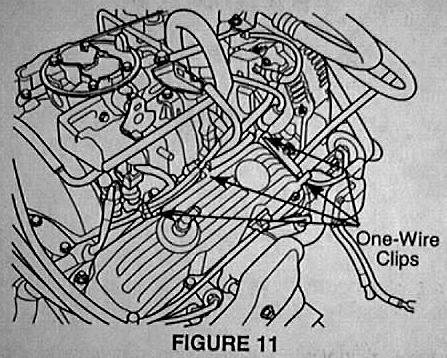
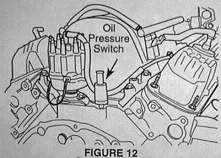
A – Coil Wire Routing (Fig 11 & Fig 12).
- Remove the coil wire from the distributor cap terminal.
- Remove the coil wire from the right rear five-wire clip, the center three-wire clip, and the front one-wire clip on the right valve cover.
- Install 3 one-wire clips along the top and front of the valve cover studs (Fig 11).
- Route the coil wire starting from the ignition coil working toward the distributor. Any excess wire should end up at the distributor end.
- Install the coil wire into the one wire clips. This may be easier to perform while the coil wire is loose from the valve cover and before the one-wire clips are attached to the valve cover studs.
- Cut the ignition wire convolute into three lengths: two at 4″ (101.5 mm) long and one at 3.25″ (82.5 mm) long.
- Slit and install the three sections of convolute onto the coil wire between the clips. Install the 3.25″ section at the front of the right valve cover. Install the 4″ sections along the top side of the right valve cover. This may be easier to perform while the coil wire is loose from the valve cover and before the one-wire clips are attached to the valve cover studs.
- Route the distributor end of the coil wire down and behind the intake manifold in front of the oil pressure switch (Fig 12).
- NOTE: The coil wire must be a minimum of 1″ away from any other ignition wires. This may require the coil wire to be routed under the vacuum and/or wire harnesses in the right rear corner of the intake manifold.
- Route the distributor end of the coil wire up the side of the distributor cap and onto the coil wire tower terminal.
- Position the original piece of coil wire convolute so it protects the wire against chafing with components at the rear of the engine.
notes:
Policy: Reimbursable within the terms of the warranty.
Labor charge: V6 …… 0.2 Hrs.
V8 …… 0.4 Hrs.